Capacitors do not behave the same as resistors. Whereas resistors allow a flow of electrons through them directly proportional to the voltage drop, capacitors oppose changes in voltage by drawing or supplying current as they charge or discharge to the new voltage level. The flow of electrons “through” a capacitor is directly proportional to the rate of changeof voltage across the capacitor. This opposition to voltage change is another form of reactance, but one that is precisely opposite to the kind exhibited by inductors.
Expressed mathematically, the relationship between the current “through” the capacitor and rate of voltage change across the capacitor is as such:

The simplest RC circuit is a capacitor and a resistor in parallel. When a circuit consists of only a charged capacitor and a resistor, the capacitor will discharge its stored energy through the resistor. The voltage across the capacitor, which is time dependent, can be found by using Kirchhoff's current law, where the current charging the capacitor must equal the current through the resistor. This results in the linear differential equation
 .
.
where C= capacitance of capacitor.
Solving this equation for V yields the formula for exponential decay:

where V0 is the capacitor voltage at time t = 0.
The time required for the voltage to fall to  is called the RC time constant and is given by
is called the RC time constant and is given by
- Capacitors are said to be connected together “in parallel” when both of their terminals are respectively connected to each terminal of the other capacitor or capacitors. The voltage ( Vc ) connected across all the capacitors that are connected in parallel is THE SAME. Then,Capacitors in Parallel have a “common voltage” supply across them giving:VC1 = VC2 = VC3 = VAB = 12VIn the following circuit the capacitors, C1, C2 and C3 are all connected together in a parallel branch between points A and B as shown.
- When adding together capacitors in parallel, they must all be converted to the same capacitance units, whether it is uF, nF or pF. Also, we can see that the current flowing through the total capacitance value, CT is the same as the total circuit current, iTWe can also define the total capacitance of the parallel circuit from the total stored coulomb charge using the Q = CV equation for charge on a capacitors plates. The total charge QT stored on all the plates equals the sum of the individual stored charges on each capacitor therefore,
AC Inductor Circuits
- Inductors do not behave the same as resistors. Whereas resistors simply oppose the flow of electrons through them (by dropping a voltage directly proportional to the current), inductors oppose changes in current through them, by dropping a voltage directly proportional to the rate of change of current. In accordance with Lenz’s Law, this induced voltage is always of such a polarity as to try to maintain current at its present value. That is, if current is increasing in magnitude, the induced voltage will “push against” the electron flow; if current is decreasing, the polarity will reverse and “push with” the electron flow to oppose the decrease. This opposition to current change is called reactance, rather than resistance.Expressed mathematically, the relationship between the voltage dropped across the inductor and rate of current change through the inductor is as such:The expression di/dt is one from calculus, meaning the rate of change of instantaneous current (i) over time, in amps per second. The inductance (L) is in Henrys, and the instantaneous voltage (e), of course, is in volts. Sometimes you will find the rate of instantaneous voltage expressed as “v” instead of “e” (v = L di/dt), but it means the exact same thing. To show what happens with alternating current, let’s analyze a simple inductor circuit:
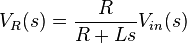
- By viewing the circuit as a voltage divider, we see that the voltage across the inductor is:and the voltage across the resistor is:
Current
The current in the circuit is the same everywhere since the circuit is in series: - T=L/R
- with Dj matildo




Walang komento:
Mag-post ng isang Komento